Build Guide

Contact: ken.wessen@gmail.com

Cherchez la FM is a 4 oscillator Eurorack FM voice module, offerring direct panel control for nearly every aspect of the voice configuration:
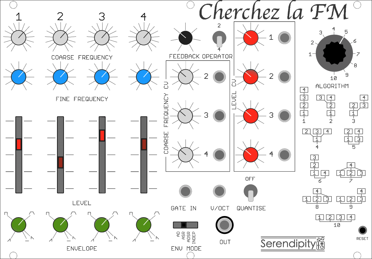
Additionally, a selectable MIDI mode offers support for 16 voice polyphony (with velocity, mod-wheel, aftertouch and pitch-bend).

Twenty distinct algorithms are provided — including a limited selection that employ waveforms other than sine, and a non-FM 4 oscillator option with sine and triangle based variable wave folding. These options are shown in the algorithm illustration above.

Some more detail of the interface is in the Control section at the end of this guide.

Video Demo

Here is a demo of the initial prototype of the CLFM module.

For an interactive introduction to FM synthesis and algorithms, see the FM Synthesis section in my online Constructive Synthesis book.

Hardware Design

The Cherchez la FM module uses just a single board, with a Teensy 4.1 performing the calculations, a PCM5102A breakout for the audio generation, various controls and sockets, surface mount components on the bottom, and a fairly standard 10-pin Eurorack power connection.

Schematic

Panel

Top layer layout

Bottom layer layout

Bill of materials

SMD Parts

DesignatorComponentFootprint
C1 C10 C12 C13 C15 C17 C181nFC0603
C5 C6 C8 C14 C16 C19 C20 C280.1uFC0603
C92.2nFC0603
C1122pFC0603
R1 R2 R3 R4 R5470R0603
R61K69R0603
R710R0603
R83K32R0603
R23169KR0603
R2456KR0603
R55261KR0603
R621KR0603
D2 D151N4148SOD-123
D1 D31N5817SOD-323
R10 R11 R19 R22 R25 R28 R30 R34 R38 R42 R53100KR0603
R12 R15 R21 R29 R33 R37 R4191KR0603
R13 R14 R17 R18 R20 R26 R27 R31 R32 R35 R36 R39 R40 R4330KR0603
IC2 IC4MCP6004SO14
IC3TL072DSO08

Suggested non-SMD Parts

DAC

PCM5102A breakout with footprint as shown in the following image:

Digikey

QtyComponentManufacturer part num.Digikey part num.
1TEENSY 4.1 (HEADERS)DEV-169961568-DEV-16996-ND
1SWITCH ROTARY 2-12POS 0.4VA 28VMRK112-A360-2372-ND
1RES 10 OHM 1% 0.6W AXIALLR1F10RA105948CT-ND
4SLIDE POT 10K OHM 0.1W TOP 30MMPTL30-15R0-103B1PTL30-15R0-103B1-ND
1SWITCH SLIDE SP4T 300MA 125VSLB1470679-2621-ND
2CAP ALUM 22UF 20% 50V RADIAL50MS722MEFC6.3X71189-2307-ND
2CAP ALUM 10UF 20% 50V RADIAL50MH710MEFC6.3X750MH710MEFC6.3X7-ND
12.54MM(.100) DUAL ROW BOARD STRACH87102V2002987-CH87102V200-ND
1IC REG LINEAR 5V 1A TO220ABMC7805CTGMC7805CTGOS-ND
1BC550 TRANS NPN 45V 0.1A TO92-3BC550CTABC550CTACT-ND
110V IC VREF SHUNT 0.1% TO92-3LM4040AIZ-10.0/NOPBLM4040AIZ-10.0/NOPB-ND
1CONN RCPT USB2.0 TYPEA 4POS R/AAU-Y1005-2AE11191-ND
16MMx6MM TACT SWITCH 13MM ACTUATOR2-1825910-7450-1642-ND
Also, I strongly recommend using female headers on the PCB for the Teensy.

Thonk

QtyComponentPart number
8B10K - CENTRE DETENT - D shaft - Alpha Vertical 9mm PotentiometerRD901F-40-15F-B10K
12B10K - D shaft - Alpha Vertical 9mm PotentiometerRD901F-40-15F-B10K
10Thonkiconn Mono 3.5mm Audio JacksPJ398SM
1Knurled Nuts (Bag of 50 pieces)
2DWB1 - SPDT ON-ON - Dailywell Mini Toggle Switch1MS1T1B1M2QES
20Black Small Unskirted D - Sifam Plastic KnobDR110
1Small Black - Sifam Plastic CapC111
4Small Blue - Sifam Plastic CapC111
7Small Grey - Sifam Plastic CapC111
4Small Green - Sifam Plastic CapC110
4Small Red - Sifam Plastic CapC111
110-16 Pin Eurorack Power Ribbon Cable

Construction

Follow these steps to construct the CLFM board.

At each stage carefully check continuity according to the schematic, orientation of components, and ensure there are no short circuits.

The Teensy goes on the underside of the board. The outer pins and parallel inner pins are needed.
Next solder in place the Eurorack power components.
The rotary potentiometers, jack sockets and toggle switches are easiest to add next. Use the panel to guide their placement. The coarse and fine frequency pots (the top two rows) are centre detent, since the neutral position is vertical. If you use the bi-polar option for the feedback, (where negative feedback makes for an increasingly square waveform) then you may wish to use a centre detent pot in this postition as well. Note: if you are using the short actuator SLB1470 switch for the envelope toggle, do not connect it at this time.
Solder the controls in place.
The algorithm control and envelope mode switch are a little trickier to place. In particular, the envelope mode switch must be raised as much as possible so it can be reached when the panel is in place.
Add the remaining components — the transistor, trimpot, and reset tact switch. Finally, solder headers onto the DAC breakout board, and then solder it onto the main board.
Here is the top view of a fully populated board.
Place the panel, fasten the nuts, and put on the potentiometer knobs.

Firmware

The firmware and hardware source files are hosted on GitHub, and can be found here.

The code will build with a standard install of Teensyduino, since the required libraries: ADC, Audio, Bounce2, Encoder, MIDI and USB MIDI support are all included out of the box.

The FM library code is in the src subdirectory.

Important! Do not attempt to connect the Teensy's micro-usb port to your computer while the module is being powered by the 10 pin header. It is quite handy to be able to use the usb Serial port while the module is in a rack, but to do so you need to disconnect the usb power — either by using a special usb cable with the power wire cut (usually coloured red), or by cutting the jumper on the Teensy board that connects VUSB and VIN.

Calibration of the V/Oct CV input is required. Easiest is to adjust the following section of code in the main .ino file:

		...
		// Serial.println(saveraw);
		/*
			Calibration data
			C2 input is 33
			C7 input is 3489
			scaling factor f ~ 60 / (3489 - 33)
			pitch_cv = (raw - 33) * f;
		*/

		const float fbase = 33;
		const float f = 60.0 / (3489 - fbase);
		...
		

Uncomment the saveraw output and see the values when playing C2 and C7. Use the measured values to calculate an appropriate scaling factor.

There is also a trim pot on the underside of the board for hardware-based scaling adjustment.

The FM code is quite computationally expensive, but well handled by the Teensy 4.1 at its default clockspeed of 600MHz. If you wish to overclock, be aware of the extra current required, and the power (I²R) going through the 10Ω resistor R9.

Control

Nearly all control of the module is straightforward and immediate, available by directly manipulating the knobs, sliders and switchs on the panel.

However, there are some aspects that are less obvious and somewhat hidden, and I will describe those here.

Envelopes

I use 4 pots for the envelopes as follows: First I use a slide switch to select the envelope "mode" - one of AD, ASR, ADSR or Independent. Then, in each mode, the 4 pots are used in different ways.

Algorithms 11-20

The 10 basic algorithms are shown on the front panel, and the feedback operator switch allows you to choose whether feedback should be applied to operator 2 or operator 4.

However, a straightforward implementation of the operator 2 feedback alternatives would mean some cases are redundant. Specifically, algorithms 14, 15 and 20 would just just relabellings of algorithms 4, 5 and 10 respectively. I thought it would be better to make them provide genuinely different sonic possibilities, and so I implemented the following idea that works well, provides plenty of additional sound possibilities, and doesn't require any complicated or magic interaction with the controls.

Algorithms 14, 15 and 17 introduce operators with triangle or square wave oscillators to provide variation from their operator 4 feedback analogues, as shown by the small illustration in the top right of their box in the above figure.

More signifcantly, algorithm 20 now has 2 sine wave oscillators and 2 triangle wave oscillators, and the fine tuning controls are overridden to perform wave folding. A clockwise rotation folds the wave symmetrically, while an anti-clockwise rotation folds asymmetrically.

Secret Menu

The "secret" menu is accessible by pressing and holding the reset switch. The Slider LEDs will light in turn, and releasing will select the associated option: In MIDI mode, CC1 will also relatively raise or lower the level of all modulators. Velocity and pitch-bend are supported.

Serial connection

A small number of commands can be sent over the usb serial port.

Congratulations! You're done.