Although the boards can simply be stacked vertically, they are designed to fit the Pactec PT-8 enclosure.
Two additional boards function purely as panels — a top panel for the controls and a
rear panel for the connections.
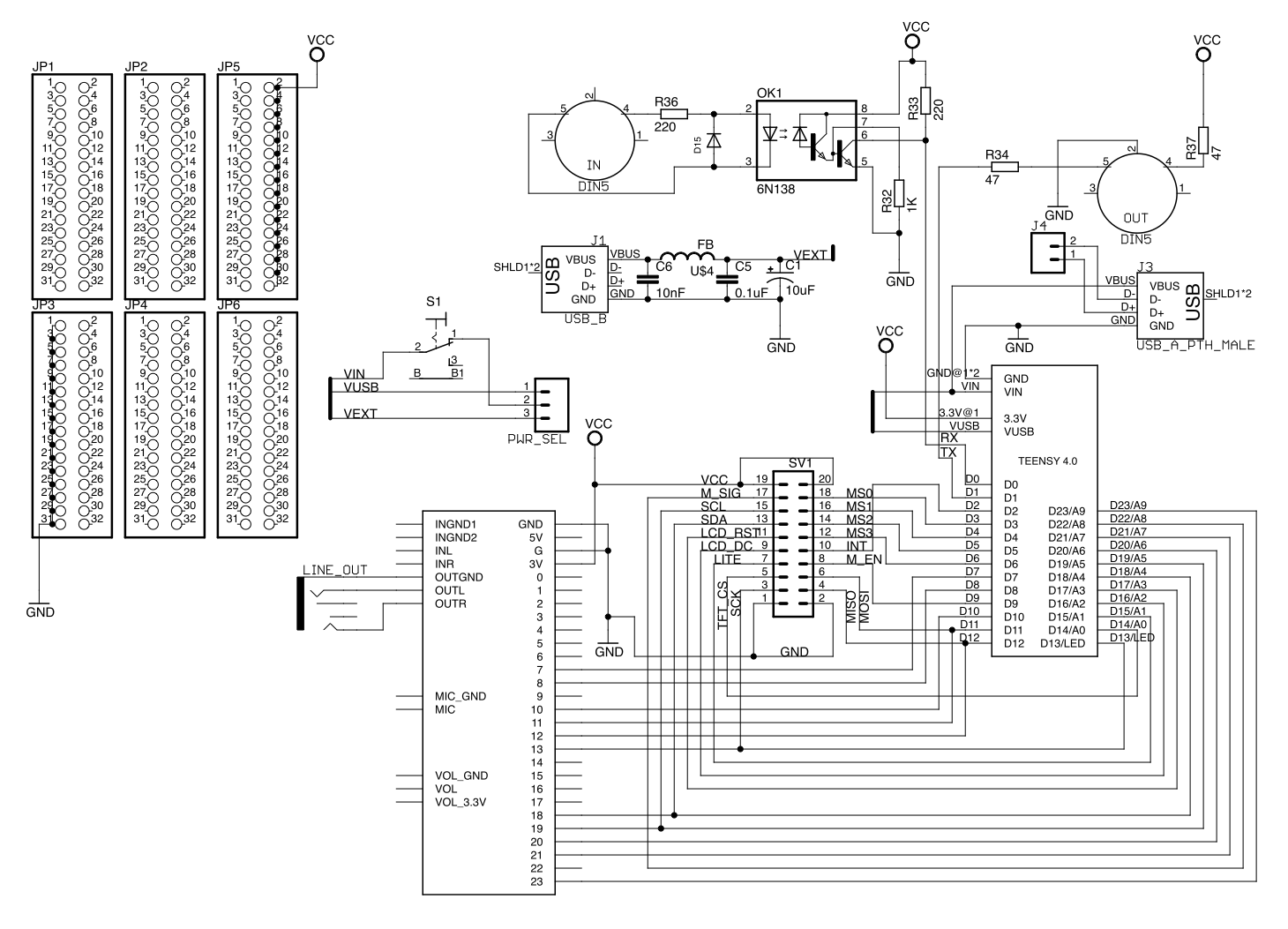
Building the Lower Board
Follow these steps to construct
The EUCLIDEAN lower (microcontroller, audio and I/O) board.
At each stage carefully check continuity according to the schematic,
orientation of components, and ensure there are no short circuits.
Components and panel for the lower board

Solder the pin headers to the Teensy and Audio Shield as follows to
ensure proper alignment with the rear panel holes when placed in the sockets


Solder the resistors and diode first

Then the other low-profile components

The capacitors and ferrite-bead for the power input circuit

The MIDI, USB and interconnect sockets

Solder the sockets for the Teensy and Teensy Audio Shield, taking care to keep them vertical.
Also the power select header to choose between power from the dedicated USB power input
(best when complete because you can provide enough current to drive a MIDI controller from the
USB MIDI port), or the Teensy USB input (more convenient if regularly re-programming the Teensy)

Cut between the pads as shown to disconnect the USB voltage and the Teensy voltage input

Then solder wires to connect the USB host pads and the USB voltage

Place the Teensy and Teensy Audio Shield into their sockets to complete the lower board.
The prototyping area provides a line of ground holes, a line of 3.3V holes, and multiple other 2.54mm holes,
and could be particularly useful
for providing additional controls connected to the extra pins on a Teensy 4.1

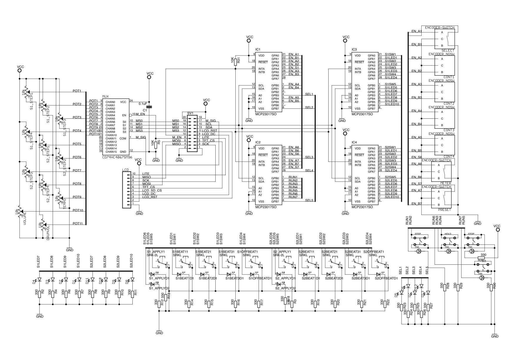
Building the Upper Board
Follow these steps to construct
The EUCLIDEAN upper (controller) board.
At each stage carefully check continuity according to the schematic,
orientation of components, and ensure there are no short circuits.
Components and panel for the upper board

Solder the PB86 switches — take care with the LED polarity
(the ground pin is on the right hand side for all diodes except the two LED switches where the
inner two pins are ground)

Add the other switches and the rotary controls

Place the upper panel (with some knobs to hold it) and check alignment


Solder the interconnect socket and the diodes, using the panel to ensure the diode height is correct

Solder the LCD pins, add spacers to adjust the height, check alignment and all diode heights.
Check all rotary controls turn easily and widen holes if necessary


Optionally add a bypass capacitor to the MUX

Secure the top panel and upper board to the enclosure and add the knobs


Secure the rear panel and lower board to the enclosure


Add the connecting cable, then complete the enclosure


 The EUCLIDEAN